So I began with tracing down where the stock ballast puppy wires went to. I found that they went under the center of the floor and then came up into the dash area along the lefthand side of the helm. The wires are bundled together with other wires in some black corrugated conduit. I found it helpfull to remove the left panel by the drivers feet to gain better access to wires coming up from the floor. To make sure I was tracing the right wires, I used a tone generator/LAN Tracer that I had. Not really meant for eletrical but works on occassion. It sends a tone down the wire and has a probe that you use to pick up the sound at the other end of the wire. Using this I was able to identify easily which wires were coming from where the pumps are located. I wasn't worried about the stock switch wiring so I decided to just clip the wires where they would be easy to access and then extend them to the length I needed for the new switch wiring.

Once I identified the old stock pump wires I then needed to find an additional 10 guage pair for the other Johnson pump. The wires that were used for the stock aerator pumps and sprinkler valves are only 16 guage so they will not be sufficient for the new Johnson impeller pumps. I was eventually able to locate a set of 10 guage wires that were stubbed under the rear bench seat. These wires were installed from the factory to be used for additional accessories. Thanks Centurion! The wires had a gray harness on the end of them as shown in the following picture.

I cut the gray harness off since I will not be using it and then attached my tone generator to them. The wires followed the same route as the stock pump wires I previously mentioned. With wires for each pump now located, I connected the wires to each pump using 10 guage butt connectors. I then extended the wires as mentioned above and ran them out through the switch panel.
It made it fairly convenient to have the main wires already ran. But you'll still need some additional 10 guage wires for the hot and ground wires from the switch to the fuse and grounding block. My father in law had an assortment of 10 guage electrical wire on hand so that is what I used. He even had the right colors. But the colors don't really matter as long as you label or keep track of what is going where.
I ran a short piece of 10 guage wire for each switch from the fuse panel up to the switch panel. My fuse panel uses resettable breakers instead of typical fuses. This is a nice feature if you ever blow a fuse which these impellers can tend to do. If one of these blows, you simply press the button back in and you're good to go. You need two fuses or breakers rated at least 25amps for this install. My starboard breaker was already rated at 30amps so I used that one for the starboard pump. My port breaker was only rated at 5amp so I ordered a new 30amp breaker from my local marine shop for the port pump. The power from the battery is already daisy chained between each of the breakers so you can leave those alone. You just need to run a wire from the port and starboard breaker up to each switch. Here is a picture of my breaker/fuse panel and the orange wire I ran for the starboard switch.

Next, I ran a short piece of 10 guage wire from the grounding block out through the switch panel. The grounding block is located up under the dash panel. You'll need a 10 guage ring connector for the end of the ground wires to attach them to the grounding block. Here's a picture of my grounding block.
Once all the wires were ran, I put a 10 guage female spade connector on all the ends. Now onto the switches! The Johnson pumps I ordered did not come with any switches and the stock switches will not work for these pumps. The switch needs to be a double pole-double throw type switch. When you order your switches, make sure they are also the right size to fit into your dash. The stock Centurion switches are Contura switches. Here is a link to the Contura switches I purchased for this install.
Contura 12981 - 3 position On/Off/On switch
The new Contura switch will fit into the stock Centurion switch holes. The covers on the new switches were different than the stock Centurion switches but since they are the same brand it makes it easy to just switch the covers with the stock covers. To remove the cover from the switch just use a small flat head screw driver to release the tiny tab on each side of the switch cover that holds it onto the base. This was easy to do and made it so I could use my new switches but have them look exactly like the stock ones. Very Nice!
The switch wiring instructions that came with the Johnson pump are helpful but are not exact for this type of switch since the post numbering is slightly different and also my switch has an LED. So use the pump instructions only as a general guide.
The following diagram shows how to wire the new Contura switches I listed above.

Note that the dotted lines in the diagram are representing jumper wires between posts. For example, for the port switch you connect the Red wire from the pump to post 6 and then run a wire from post 6 to post 1. This allows the switch to reverse polarity to the pump which makes it spin in reverse. Also note the jumper wire going from post 5 over to post 7. This is to get the LED to work. The two switches are essentially wired the same with the exception of posts 3 and 6. Those are wired opposite from one another due to the direction each pump is mounted under the seat.
The part of all this that had me scratching my head for a while is how to get a jumper wire between two posts. There wasn't enough room in a 10 guage female connector to fit two wires (one from the pump and the other being the jumper wire). I ran all over town trying to find a solution. I went to home depot, lowes, Auto Zone, and a local electrical supplier but they didn't have anything that would work. I then went to a marine shop nearby (Fred's Marine) and told them what I was trying to do. They had exactly what I needed! It is a spade connector that has a female end and then hooks around into another male spade. I hope that made sense because this isn't a very good picture of the part.

Here's a picture with the pump wire connected to it.

And lastly, here's a picture with it connected to the back of the switch (before I ran the jumper wire).

I was very happy when Fred's Marine brought that part out to me. They didn't have any for sale on the shelves but had some in the back for their own service work. So be sure to ask the service guy at your marine shop if you go looking for something like this because you might not find it available on the shelf.
I was then able to finish my switch wiring and decided it would be a good time at this point to test them out before I got everything put back into the dash. So I reconnected my battery and filled a 5 gallon bucket with a little bit of water. I then made sure all my valves were closed on my manifold and put one of my aux hoses into the bucket of water. I first turned my port switch to the Fill position and it blew bubbles in the bucket. I then switched it to the Empty position for a brief second and it began to suck water up the hose. Great! This meant that the wiring was correct. If I would have seen the opposite results then that would have meant that the wires coming from the pump needed to be swapped on the back of the switch. I would have needed to swap the wires on posts 3 and 6 (including their corresponding jumpers to posts 1 and 4). The switch was wired correctly though so no worries. I then did the same test with the starboard switch/pump. Everything worked great. The pump worked in the right direction and the LED on the switch also worked.
After I had the switches wired and tested, I then attempted to fit them back through the switch panel. I soon realized that due to the size of the wires and the extra space taken by the jumper wires that the switch would not fit. That was easily solved by removing the switch panel from the dash and then disconnecting the jumper wires from posts 3 and 6. That gave me enough room to put the switch housing into the panel and then I was able to reattch the wires to 3 and 6 from behind with the switch panel removed.
I then attempted to attach the switch panel back onto the dash and ran into another hang up. The wires from the back of the switches kept hitting the fiberglass backing behind the dash. There are only a series of randomly placed access holes in the backing. My switches didn't line up with one of the access holes so they were hitting the backing and causing the switches to get all tweaked. It didn't look or function well. This was due to the larger guage wires and also the jumper wires. These don't bend and flex into the space like the smaller stock wires did. Here's a picure from under the dash that shows the round access hole in the backing.

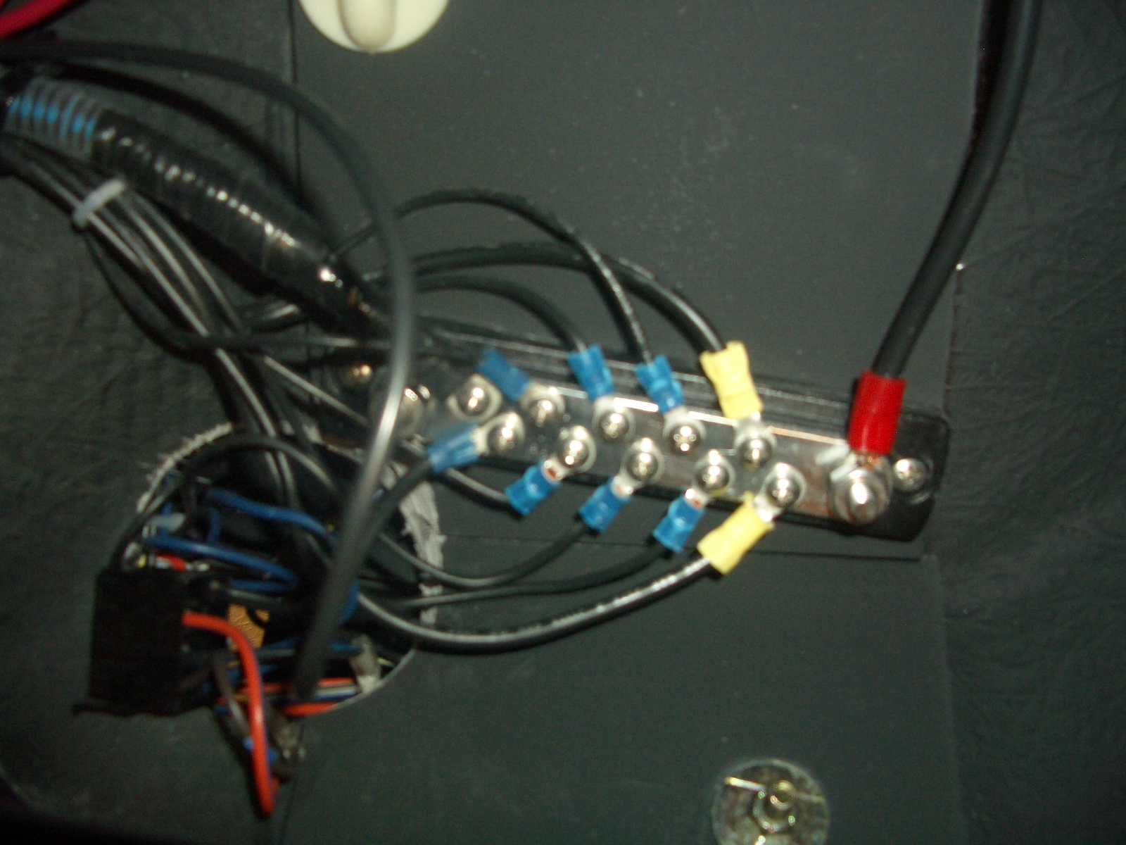
I didn't feel like making any of the holes bigger. I thought that would be difficult to do without damaging all the wiring running through there. So my solution was to move my ballast switches to a different location in the dash panel where they would line up with one of the access holes in the backing. This only meant that I had to move each of them one spot to the left. The following picture shows their final installed location.

Whew! All done! Now it is just time to clean up all the wire clippings etc.
No comments:
Post a Comment