This blog is intended to be used as a reference for others wanting to install a custom ballast into their boat. Many of the ideas in this install were taken from other boat owners who shared their custom install stories. I am grateful to all those who have shared. Hopefully this blog will continue to share the ideas and possibly a few more. Each person's ballast install will be different depending on their boat, budget, and needs. This ballast install is not meant to be an example of the "right" way or the "best" way. It is just a design that I felt would work best for my needs and within my budget.
Two of the main resources I used when doing the design for this ballast install are linked below.
BigCatPT - Centurion Avalanche Ballast Install Blog (great resource)
H20King - Centurion Falcon V Ballast Install (thread from CenturionCrew.com)
This ballast install is for a 2009 Centurion Falcon V but can be adapted for almost any wake boat. This design will allow me to fill up approximately 2500LB of ballast on either side of the boat to get the boat really leaning to the side to hopefully produce a very nice surf wave. Of course, the sacs could also be partially filled to help with a wakeboard wake as well.
In the end, this ballast will consist of the following possible ballast:
1100LB sac in the rear locker
225LB hard tank under side seat bench
400LB sac on top of side seat
400LB sac on observer seat or on floor behind driver (depending on surf side)
400LB integrated bow sac under bow seats
The ballast listed above is only meant for good water conditions and with a small crew. If you have a large crew then you obviously don't need as much water weight. Also, do not use this much weight in bad water conditions. Depending on the boat, it can be easy to take on water into the boat if weighted down in rough water. Use your best judgement out there. It doesn't take this much weight to get a surf wave. I just designed this system so that I had the capability to lean the boat as much as possible when conditions permit.
With that said, I hope you enjoy this blog. It is quite lengthy so I tried to split it up into manageable sections. Have fun out there!!
Stock Setup
Before I get into the nuts and bolts of the new design, I figured it may be helpful to tell you what the stock setup was.
The 2009 Centurion Falcon V came stock with two 250LB tanks. One under the port bench seat and the other under the starboard bench seat. The tanks are listed as 250LBs but they are actually more in the 215LB range. The boat came with a single Jabsco Ballast Puppy impeller pump which is used to fill both hard tanks. Water is diverted into each tank by using sprinkler valves which are open and closed by each switch. The tanks are emptied via an aerator style pump directly attached to each tank. So the empty times are faster than the fill times. The Jabsco pump is supplied by a 1" thru hull inlet. 1" hose runs between the pump and the sprinkler valves. 3/4" hose is ran from the sprinkler valves to each stock tank and also used for each tank's drain hoses. In addition to the stock ballast, my Falcon V has a SwitchBlade wake enhancer which is an option through Centurion. The switchblade is incredible for wakeboarding but is not quite ideal for surfing. It helps but is not enough to produce a decent size wave and surf pocket.
The 2009 Centurion Falcon V came stock with two 250LB tanks. One under the port bench seat and the other under the starboard bench seat. The tanks are listed as 250LBs but they are actually more in the 215LB range. The boat came with a single Jabsco Ballast Puppy impeller pump which is used to fill both hard tanks. Water is diverted into each tank by using sprinkler valves which are open and closed by each switch. The tanks are emptied via an aerator style pump directly attached to each tank. So the empty times are faster than the fill times. The Jabsco pump is supplied by a 1" thru hull inlet. 1" hose runs between the pump and the sprinkler valves. 3/4" hose is ran from the sprinkler valves to each stock tank and also used for each tank's drain hoses. In addition to the stock ballast, my Falcon V has a SwitchBlade wake enhancer which is an option through Centurion. The switchblade is incredible for wakeboarding but is not quite ideal for surfing. It helps but is not enough to produce a decent size wave and surf pocket.
The Problem
When surfing, I primarily surf the starboard side since I am goofy footed. My typical ballast setup when surfing (with only 2-3 passengers and smooth water) is to fill a 750# Launch Pad sac in the rear starboard locker, 350# Launch Pad sac on the starboard bench seat, 350# Launch Pad sac on the floor between the back of the driver's chair and the starboard bench, stock starboard tank filled, and a 400# integrated Fly High bow sac located under the bow seats. So this is 4 sacs that I am manually filling each time I surf. I currently use a Fly High Tsunami pump to fill the bow sac, a Launch Pad Uber pump to fill the 750# locker sac, and a single Mayfair aerator pump to fill the two 350# sacs. That is 3 portable pumps running at the same time. And the 12v cord for all 3 pumps are plugged into the single 12v socket located near the driver's feet. The Falcon V only has one 12v outlet stock. So I use a 12v splitter to run all 3 pumps at once.
As you can imagine this is a big spaghetti mess of power cords and pump hoses. About every two minutes my son or someone else is sure to trip over one of the power cords just enough that it comes disconnected. So unless I'm with someone else who is familiar with filling ballast sacs, I'm generally running all over the boat checking how full the sacs are and making sure the pumps are still going, and if the sac is full, I'm trying to quickly get through all the spaghetti and through the passengers to unplug the pump before the sac wants to burst. Then there's the usual water that escapes from the sac when removing the fill pump before you can get the cap back on the sac. This made it so I was always airing out my carpet when I get home after each surf trip. That is a good thing to do anyways but I was usually mopping up excess water caused by the overflow.
This took a considerable amount of time and headache to fill all the fat sacs. Also, I'd sometimes have to jump through all these hoops more than once a day if we were to switch everything to the port side for regular footed riders. This was too much mess and too much time wasted on the water dealing with pumps.
The Solution (Design)
The solution to my problem previously discussed is to install a custom ballast system into the Falcon V. There are many ways to design a custom ballast system. Decisions need to be made regarding what type of pumps to use (aerator vs. impeller), what sacs to use, what type/size hose to use, how many inlets, etc, etc. I've researched many different types of designs and almost every one of them does their job just fine. There's no one "best" solution out there. You just need to decide what will work best for your situation given the pros/cons of each. When designing your own ballast, try to think of every detail like where you plan on placing sacs, where your plumbing will be ran, how fast you want to fill and empty, etc. I think I changed my design at least a dozen times as I drew it up and then thought of something to change to make it more flexible or meet other needs. I won't go into much discussion regarding the different types of setups but will address it some. Again, I in no way claim this design is the best...it is just one that I felt would work for what I'm trying to accomplish.

The Pumps:
My design will consist of two Johnson Ultra Reversible Ballast pumps (13.7GPH) supplied by the single stock 1" inlet. I will be removing the stock Jabsco ballast pump, sprinkler valves, and aerator pumps. I chose the impeller type pumps over the aerator type pumps for two reasons: 1) I wanted to be able to install some auxilary fill lines which would allow me to fill and empty extra fat sacs on the seats using the same hose tied into the ballast system. This is not possible when using aerator pumps due to the fact that they are not reversible and are not self priming. 2) I was concerned that it would be difficult to mount aerator style pumps below the water line in my boat. The Falcon V has a much shallower hull than the other Centurion models. The aerator style pumps require that they be mounted below the water line in order for them to be primed without user intervention. The aerator style pumps have a lot of advantages though including that they are quieter, draw less power, and are cheaper. If I didn't have the two concerns listed I would probably have gone with aerator style pumps. From what I've read regarding other's experiences, the single 1" stock inlet is sufficient to supply water to both Johnson impeller pumps. If I see any restrictions then it will be easy to add another inlet to the system at a later time.
The Manifold:
I wanted the system to be as flexible as possible. I will have quite a few additional sacs to fill but didn't have the budget for more than two pumps so I wanted to be able to pick and choose where the water is directed. I also wanted to be able to fill any sac with both pumps but also have the flexibility to fill with one pump while emptying another sac with the other pump. This required the use of several valves. I decided to build these valves into a manifold that will be centrally located behind the rear seat bench on the front engine wall (the same place the stock sprinkler valves were located). Given the amount of lines required, this manifold was going to be fairly large in width. My max width on my engine wall is 3 feet. So I had to ensure that my manifold would fit within that size limitation. As I went through the design process, I realized that I would not have enough room for a manifold unless I removed the stock sprinkler valves. There wasn't enough room to relocate them. So that was my main reason for removing them....If I could make it work, I would have left the stock system untouched. So the manifold valves will consist of 2 lines for the starboard rear locker sac, 2 lines for the port rear locker sac, 1 line for the integrated bow sac, 1 line for the stock starboard hard tank, 1 line for the stock port hard tank. The manifold will also have a valve placed in the center as shown in the diagram which will allow me to isolate the two pumps by closing the ball valve. I refer to this as the isolation valve. To add flexibility, each rear locker sac will have 1 line on each side of the isolation valve as shown in the diagram. This will allow me to get max flow into each sac when filling with both pumps. With 7 total valves on the manifold, it can become a bit confusing at first to know what goes where. My plan is to use a sharpee to label each valve to help reduce any confusion.
The Fat Sacs:
The custom ballast system will consist of a Fly High Jumbo 1100# sac in each of the rear lockers, a Fly High Integrated bow sac under the bow seats, and two Fly High 400# sacs to be placed on the floor or seats as desired. Total ballast weight per side for surfing (including stock ballast) will be approximately 2500LB. The bow sac will be filled/drained by a single line which will be split using a Y adapter. This will make it so that the bow sac is filled and emptied from both legs of the bow sac. I will discuss this more in the install sections of this blog. The two rear Jumbo sacs will be supplied by two lines (one at the base of the bag and one on top). The 400LB auxilary sacs will be filled using the auxilary lines as discussed later and will have a Fly High check valve (W744) to prevent water from escaping when the pump hose is removed.
The Hose:
The ballast system will use 1" hose for all fill lines with the exception of the stock hard tanks. The stock hard tanks will be filled using 3/4" hose. I did this so I could reuse the existing stock hose and save a few pennies. I also figured the small stock tanks will be full before the larger Jumbo sacs so I didn't worry about the smaller line reducing my overall fill times. The two Jumbo sacs and the bow sac will each have a single 3/4" hose used as a vent. Yes, I'll be filling the Jumbo sacs with two 1" lines and only venting with a single 3/4" line. I don't foresee that as being a problem since the pumps are not producing more pressure than a single 3/4" vent line can handle. 1" hose will also be used for the drain lines that direct water over the side of the boat when emptying.
The Check Valves:
This ballast system uses a number of check valves for two different purposes. Check valves are placed on each vent line with the exception of the vents for the stock hard tanks. The purpose for check valves on the vent lines are to allow the bags to completely "raisin" when emptying. Essentially, it allows the pumps to completely collapse the sac since no air will be drawn through the vent line when emptying. The two other check valves are placed on the inlet side of the impeller pumps as shown in the diagram. This is done so that water is redirected overboard when the pumps are emptying. Many people choose to just empty back out the thru hull in the bottom of the boat. That works well but I like to have the visual and audio confirmation that water is still flowing through each pump. So each pump will have its own discharge line over the side of the boat. Another check valve is placed on each drain line so that the pumps do not suck in air when filling.
Auxiliary Lines:
As mentioned earlier, the ballast system will consist of two auxilary lines. These lines can be used for filling and emptying sacs that are placed on the floor or seats of the boat. Each auxiliary hose will have a manual shut off valve at the end of the hose. This eliminates the need to have the lines coming off the manifold and allowed me to stay within the 3 foot manifold width limitation mentioned earlier. The aux lines are split off each pump's main line before it is fed into the manifold. I used a Y rather than a tee where the line splits to help direct the flow a little better. Others have previously used a tee and have said that the force from the pump makes it so that most of the flow goes through the straight part of of the tee rather than up the top. If there is some resistance further down the line then that doesn't become a problem. I'm hoping by using a Y that it will help direct the flow of water more evenly.
Stock Plumbing Removal
My design will use two new Johnson Ultra ballast pumps for filling and emptying all ballast and will include a new manifold with ball valves for everything. So the stock plumbing is no longer needed. Essentially everything needs to come out except for the hard tanks and I'll reuse a small portion of the existing hose later on.
The first thing I did was to remove the stock ballast pumps and hoses leading up to the sprinkler valves. This boat came with a single Jabsco water puppy located under the rear seat bench. Begin by removing the hose from the fittings. To do that you simply loosen the clamps and then I found it handy to heat up the hose with a heat gun to help get the stock hose off the barbs. Just be sure to be careful with using the heat gun. You don't want to direct too much heat around any electrical or other hoses in the boat. Pay attention to what you are doing and you'll be fine. Heat up the pipe slowly until it expands enough to come off.
Once you have the hoses removed, you can now remove the stock pump. Make sure your battery is disconnected and clip the electrical wires to the pump. Be sure to leave the original wire tails so that you can either sell or reuse the stock pump somewhere else. The pump is screwed to the wall using 4 screws. Remove those and you're done under the seat bench. By the way, I found that working under the seat bench is much easier if you remove the seat hinge from the base.
Now you're ready to start removing the sprinkler valves and stock manifold. These are located on the wall in the front of the engine compartment. You basically just need to clip the wires, remove the mounting straps, loosen the hose clamps and you're good to go. Be sure to keep the mounting straps used for the original manifold. We'll use those later to mount our new manifold. Sorry this is a horrible picture.

Next it is time to remove the stock aerator pumps and hoses used for draining the stock tanks. You won't need those anymore since the new Johnson impeller pumps are reversible and will be used for both filling and emptying the tanks. The stock tanks are accessed via access panels located in the rear lockers and under each seat bench. Remove the panels and you'll see the fill and vent lines on the front of the tank and the empty pump on the rear of the tank.

The aerator pump is screwed directly to the hard tank and there is not enough room to spin it off. In order to unscrew the pump you'll have to slide the hard tank into the rear locker far enough until you can lift up the end of the tank to unscrew the pump. To do this, start by removing the fill and vent hoses from the front of the tank. Also remove the hose going from the pump and clip the electrical wires. The hose simply threads off of the pump. Next, you'll need to detach the tank from the floor by removing the 8 screws used to secure the tank. Leave the mounting brackets attached to the tank...just remove the screws threaded into the floor. Once you've done that, the tank easily slides through the rear access panel and into the rear locker. If you're like me and have antifreeze in the tank from winterizing then you'll need to be careful to not spill it once you remove the pump. I used a fluid extractor to suck some of the antifreeze out of my tanks since the stock drain pump only sucks so much out....there's still a fair amount in the very bottom of the tank. You'll need to keep the end of the tank raised up a bit while you do this so that the fluid doesn't come out where the pump used to be located. Once you have the tank pulled into the rear locker then you'll have enough room to lift up the tank and unscrew the pump.
Before you push the tank back under the seat bench, now is a good time to thread a 3/4" barbed elbow onto the end of the tank. This will be used for the new fill/empty line. I wasn't confident that the threads on the hard tank were very precision so I used a little thread seal tape around the threads of the elbow. Once you're done with that go ahead and push the tank back under the seats. Here's a picture with the 3/4" elbow attached. We'll attach the hose at a later time.

Next, remove the fill hose as it is no longer needed. The stock fill hose runs from the sprinkler valve to the front of the hard tank. Both ends are disconnected at this point so it is just a matter of fishing it out. You'll find there are probably endless amounts of zip ties to cut while you're doing this. Reattach the vent hose to the front of the tank. Be sure to inspect the end of the stock hose as I found it becomes easily damaged when removing it from the barb. Especially if you had to heat it up. I luckily found this out when I noticed a small drip of antifreeze seeping through my drain line when I reattached it. So just be aware. I suggest just snipping a few inches off of any stock hose you have to reattach. There's usually enough slack available.
Since the fill hose is no longer needed, you'll now need to plug the port going into the hard tank. I originally planned on just unthreading the stock barbed elbow and threading in a plug into the tank but it is impossible to get the stock elbow off the tank. It bumps into the elbow used for the vent lines. I couldn't see a way to unthread either of them due to how close they were to each other. This had me scratching my head how they did this at the factory. The only thing I could tell was that they thread the elbow onto the port and then that actually gets attached to a hole in the tank by melting them together. You can tell the area around the threads were melted on at some point. Anyway, so my solution to that was to use a 3/4" barbed plug and a small section of the stock 3/4" hose. Just make sure your hose is pointing up so that water doesn't pool in it and freeze during the winter. Here's a picture of what I'm talking about.

The last thing left to do is to remove the drain hose that was attached to the aerator pump from the thru hull on the side of the boat. I found it pretty difficult to fish my arm behind the front of the locker and back to the thru hulls. It takes a bit of blind surgery skills to snip all the wire ties that have to come off. Once the wire ties are cut then you can loosen the hose clamp and pull the hose off the thru hull. We'll reuse that same thru hull as a vent for the Jumbo sacs later on. Also, I found that removing the hose from the starboard side is easier if you first detach the bilge hose from it's thru hull fitting. It is hard to get to the hose clamp on the drain line if you don't do that.
Whew, the stock ballast system is now a gonner. You might find the pumps or hoses useful in your design or may choose to sell them. Now we can begin the fun part of putting the new system in.
New Manifold Install
The first thing I did after removing the stock plumbing was to build and install the new manifold. This new manifold will allow me to redirect water to and from any of the sacs and tanks. It will also allow me to isolate each pump so that one can be used to empty while the other one is used to fill. I plan to fill and empty using both pumps most of the time but wanted that flexibility.
The new manifold is a series of 1" PVC slip tees, 1" slip ball valves, and 1" slip x 1" NPT adapters. Be sure you measure where your manifold will be installed and make sure you'll have enough width. My Falcon V had 3 feet to work with and this new manifold will take up all but a couple of inches. Also, make sure none of your engine components will interfere with the lines coming off the new ballast manifold. I actually dry fit my manifold first to make sure there wasn't going to be any surprises. Once you glue the manifold together there's no turning back.
An important thing to note when building your manifold is to allow enough space between each tee so that the valve handles do not bump into each other when closed. The width of the valve handles are slightly wider than the PVC tees. So you won't be able to butt each tee up against each other. I found it was best to install each valve onto a tee before attaching all the tees together. Doing this allowed me to turn the valve to the closed position and helped me make sure I had enough gap between each tee while glueing them together.
Here is a picture of the completed manifold.

Take special care to make sure your valves are aligned straight when glueing them to each tee. You want the valve handle to be running completely parallel with the straight part of the tee it is attached to. This is mostly for cosmetic reasons. One of mine was off a bit and there's no way to fix it once the glue sets...which is very fast.
You'll also notice in the picture above that there is a valve located in the center of the manifold. This is what I call the "isolation valve". This allows me to isolate the flow from each pump. By closing the valve I can fill with one pump and empty with the other pump. By opening the valve I can supply water to all lines using both pumps together.
The elbows on each end of the manifold is where the lines from each pump will be attached. The lines for each aux sac will not be part of the manifold. They come off the main lines before the manifold as I'll show in the pump installation section.
Once you have your manifold built and the glue has setup you can go ahead and mount it in the boat. I mounted the manifold in the same location where the old sprinkler valves used to be located. The old sprinkler valves were attached to the wall using two straps. The two straps had a rubber liner to them. By removing the rubber piece I was able to use them to mount the new manifold. The straps are not big enough to go around the 1" tee without removing the rubber piece first.
Here is a picture of the manifold installed in the boat. You might have to fish your manifold into the engine compartment. There's not enough room to drop it in from the top. I had to fish mine in sideways from the port locker (with the engine divider removed of course).

Be sure to leave enough room between the top of the manifold and the metal frame of the engine compartment for the isolation valve to spin closed. It may be helpful to just mount it with it closed so that you know how high you can mount the manifold.
New Pump Installation
Now its time for the installation of the two new Johnson Ultra Reversible ballast pumps. I began by installing the hose and fittings starting from the intake and working my way up to the pumps. Shortly after the intake, I placed a 1"barb x 3/4" female thread tee in the line. This will be an access point where I can hook up a garden hose for testing the system and for sucking antifreeze through the system when winterizing. I hate crawling under the boat with a fake-a-lake.
Here is a picture showing the parts required. Tee, 3/4" NPT x 3/4" garden hose thread adapter, 3/4" garden hose cap.

The garden hose cap makes a good seal because it has a rubber bushing like a standard garden hose as shown below.

Be sure to use pipe thread tape along the threads of the adapter before you thread it into the tee. Thread tape needs to be used for any metal to plastic thread connections. Below is a picture of these parts installed.

Once that was complete, I mounted the two Johnson pumps. One to each sidewall under the rear seat bench. You'll need to make a trip to the hardware store to get some mounting screws since the Johnson's surprisingly do not come with any screws. If I remember right, I was able to use 1" #8 screws. I reused some of the stock 1" hose for part of this as you might notice in the pictures. Just work your way installing the sections of hose and fittings from the intake up to each pump. Be sure to install the check valves the right direction so that the water can be redirected overboard when emptying. This was shown in the ballast diagram on the "Solution" post of this blog.
Here is a picture showing one of the installed pumps along with the check valve, tee, and elbow used to redirect the water when emptying. This picture shows the empty line installed but I actually held off on doing that until later for reasons I'll mention when I get to that point. We'll also complete the electrical wiring at a later time.

Next, I ran a short piece of hose from the outlet side of the pump and attached a Y fitting on the end. This Y fitting is where the main line will split between the manifold and the auxiliary hose. One auxiliary hose splits off of each pump in my design. Having two aux lines isolated between pumps will give me the flexibility to be emptying one aux sac while filling another. This will come in handy when switching the ballast weight from one side of the boat to the other.
Below is a picture of the Y fitting. One leg of the Y will go up to the manifold and the other will go the the aux line which will be attached later. I chose to use a Y fitting here rather than a tee because I felt like it would help distribute the flow a little better between the hoses. When using a tee here, others have experienced that the force of the water coming out of the pump makes it so that very little water is able to go up the top of the tee....it all wants to shoot straight through. This Y fitting should help avoid that a little.

Once your Y fitting is attached, you can then run a section of hose up to the manifold. Be sure to tighten the hose clamps on your Ys securely. If you don't then water can escape when the line is pressurized. This is just due to the design of the barbs on the Y fitting.
Drilling Holes for Vents and Drains
When designing my ballast system, I tried very hard to figure out a design which would not require me to drill any holes in the boat. I kept having nightmares of me screwing something up and having to take the boat in for some serious fiberglass repair. Of course, there's my wife saying "You're going to do WHAT??" as well. I came up with a couple of different possibilities which included emptying back out the bottom of the boat (similar to what others are doing with reversible pumps), and combining vent lines into a single thru hull. All this would have worked but would have taken away from some important features I wanted in my design. I wanted to be able to empty over the side of the boat so that it would be easy to tell if sacs are empty and water is no longer going through the pumps. I also wanted to be able to tell when a sac was full. If I was to combine vent lines into a single thru hull then I wouldn't be able to tell which sac was overflowing and I'd have to visually check each sac. I didn't want to be visually checking each sac so I made up my mind and decided to take the risk of drilling the holes.
My design would require 3 new holes. I would only require 3 holes because I would be reusing two stock 3/4" thru hulls (previously used for emptying) as the vents for the new Jumbo sacs in the lockers. I would need to drill a 3/4" thru hull for the bow sac vent line located towards the bow on the port side and also would need to drill two 1" thru hulls to be used as a drain line for each new pump. I chose to use a 1" thru hull for the drain line since I was using 1" line for filling. I wanted to keep the time it takes to empty the sac close to the time it takes to fill it. So I decided to keep the hose size the same. That probably isn't necessary but it is what I went with. I used 3/4" for the vent lines because I could reuse two of the existing thru hulls and I also felt that a single 3/4" vent would be able to keep up even with the amount of water that would be fed into each sac. The two Johnson pumps will not produce enough flow or pressure to burst a fat sac with a 3/4" overflow/vent.
A lot of good information is out on the web regarding tips on how to drill a hole in a boat. Read up as much as you can on this. It also helped me to have some friends who have done this same thing before. BigCatPt and Kris K from the CenturionCrew were a big help.
The first thing to do before anything is to make sure no hoses, wiring, etc is behind where you'll be drilling. Next, use blue painters tape to mask off the area where you'll be drilling. Then I marked where my hole would be using a pencil. I used the existing thru hulls as a point of reference. Measure the distance between your existing thru hulls to make sure you have consistent spacing to your new hole. I used a measuring tape and straight edge to transfer reference points from the existing thru hulls over to my new hole. Be sure to adjust the measurements as needed if your new hole is bigger than the other thru hulls as mine is. Remember, my stock thru hulls are 3/4" but I'm adding a 1" thru hull next to them. Take the time to make sure it will look like it was done on purpose.
I was able to use a 1 3/8" hole saw for my 1" thru hulls and a 1" hole saw for my 3/4" thru hull. It helps to drill a test hole into a piece of wood to verify that you will have a proper size hole before drilling into the boat. Attach your hole saw to a power drill and put the drill in reverse. Do not use the drill in forward as the teeth will want to grab and chip the gelcoat. Take your time drilling in reverse. It will be very slow. Don't get in a hurry and apply too much pressure to the drill. Let the drill do the work.
Once your hole is drilled, you want to round the corners of the edge of the hole to avoid cracking later on. A dremmel tool with a sanding drum works well for this. Take it easy and slow doing this as well. Then be sure to cut any carpet away from the open of the hole so that it will not get caught in the threads of the thru hull when you screw the backing nut on.
Next, clean up the area and then place some 3M 5200 marine sealant on the back edge of the thru hull. Gently press the thru hull through the hole. Don't use too much sealant as it will just squish out and make a mess. You just need enough to make a water tight seal. Then thread the backing nut onto the thru hull. If your thru hull has notches in the design like mine did then it helps to have someone hold the position on the outside of the boat while you tighten the backing nut from the inside of the boat. Once that sealant sets up you won't be able to rotate the thru hull.
Here's a picture of one of my new 1" thru hull on the port side. My new 1" thru hull matches the stock 3/4" thru hulls (notice the notches in the design I talked about, make sure those are straight)
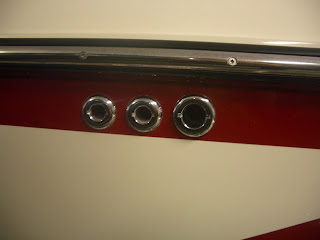
I drilled the 3/4" vent hole for the bow sac under the rub rail near the front of the windshield. This location allowed me to access the vent hole from within the storage compartment under the glove box/observers seat. Here's a picture showing the location.

If you were nervous about drilling the holes, you'll be more confident after drilling the first one and realize it isn't that big of a deal as long as you're careful. After drilling 3 of them in my boat I still don't like to do it but I am more confident now.
Routing Hoses for Vents and Drains
After the new thru hulls are installed and the sealant is cured then it is a good time to run the hoses for the rear locker sacs and also the drain lines. I decided to install those lines at this point because the vents for the locker sacs will use the existing 3/4" stock thru hulls that were originally used for the drain hoses coming from each hard tank. The thru hulls are very difficult to reach so it makes it a bit easier if you connect the vent hoses for the locker sacs first since they would be obstructed by the drain lines if you were to attach those first.
So begin with the vents for each locker sac. Many people are now running their vents to the opposite side of the boat. So the port locker vent goes to the starboard thru hull and the starboard locker vent goes to the port thru hull. This is done so that water is not lost through the vent when the boat is fully weighted down on one side. When the boat becomes weighted, the same-side vent actually becomes lower than the top of the sac and gravity along with the rocking of the boat will cause water to seek its way out through the vent. I figured this was a good idea so that is what I did as well.
I installed check valves in each vent line as close to the thru hull as I could while still allowing them to be accessed. I used 3/4" check valves supplied by wakemakers which are serviceable so I wanted to make sure they were easy to get to in the future. The check valves will allow water to be vented overboard but will close when the sac is being emptied. That allows the pump to suck all the water out of the bag without drawing in air.
Here is a picture of the vent line coming from the bow sac and out the port side of the boat. This view is from inside the observers seat storage compartment (under the glove box area).

As you can see, I routed the vent hose for the bow sac over the the divider and then down under the bow seats. There's a small opening at the top of the divider to route the hose. I recommend trying to route all your vent hoses as high as possible to help prevent water from escaping when the boat is leaning. You can also see the 3/4" check valve in this picture. Try to keep the hose between the check valve and the side thru hull sloped downward so that water will not become trapped in the short piece of hose. This will lower the chances of trapped water freezing in the hose during winter months.
After I had the rear vent lines ran then I started on routing the drain hoses. The drain hoses run from just behind each pump. Remember that I had installed check valves on the supply lines so that water would be diverted overboard when the pumps are emptying. Here is a picture of the port pump and notice the drain hose which is attached to a street elbow threaded into a 1" tee. My drain hose and fittings are all 1".

Remember to also install a 1" check valve close to where the drain hose is attached near the pump as shown in the above picture. This is needed so that the pump will not draw in air from the drain hose when it is in the process of filling the sacs. You want to make sure the pump is only sucking water and no air when filling. The check valve on the drain hose will allow water to be drained but will not allow air to be sucked back in. I originally had the check valves installed closer to the side thru hull but I found after doing a water test that the pumps were sucking in air through the check valves. I called wakemakers and they did not have any good solution. They told me that these check valves were chosen by them because they did not have a history of this type of issue like other brands have had. The only thing we could think of to try was to install the check valves closer to the pump in hopes that there would be enough suction to close the flapper and make a tight seal. A water test with the valves closer to the pump showed that it did help a bit. They still sucked some air during the initial test but I found that they closed up once some water was sent out the drain hose. Having the check valve lower in the boat allowed the remaining water in the drain hose to help keep the flapper closed when the pumps were filling.
As mentioned in a previous post, I used two 1" chrome thru hulls for my drains. I purchased them from wakemakers. When I received the 1" thru hulls I realized that the barbed end is technically meant for a 1 1/8" hose. The website isn't clear on that. The reason I bring that up is because the slightly larger barb makes it extremely difficult to get the 1" drain hose over the barb in that tight of a space. I tried to heat up the drain hose quite a bit to get it to slide over the barb but it was not working. I either made the hose too soft to work with or I didn't heat it up enough in other attempts. I struggled with it for a while. The hose I chose to use does not stretch very much. Finally! the lightbulb came on in my head. My tsunami pump uses a 1 1/8" hose and it stretches very easily. So I sacraficed a few inches off my Tsunami pump's hose and it worked like a charm. My tsunami pump won't miss it because it already had a very long hose on it. I put a 1" elbow onto my 1" drain hose and then attached the short piece of 1 1/8" hose to the elbow and then easily put it over the barb on the thru hull. Clamped everything real tight and did the same thing for the other drain hose.
I was glad when I was finished attaching the vents and drains to the thru hulls. It is not easy to get your hands back in there and still be able to see what you are doing.
Routing Sac Fill/Empty Hoses
Once I was finished routing the vent/drain hoses, I then began to route the hoses for filling/emptying. As mentioned previously, the same hose will be used for filling and emptying since my pumps are reversible. When routing your hoses, I suggest planning ahead so that other hoses don't get in your way as you work through the install. The space where the hoses attach to the manifold will be pretty tight so you don't want to be fighting other hoses that are already attached. I hope that made sense. Also pay attention to where you are routing the hoses in the storage areas. For my hoses that attached to the top of the sacs, I tried to keep those routed up high in the locker area so that they don't tend to get caught on anything that is stored in the lockers when the sacs are not being used. I routed those hoses along the base of the engine compartment and then brought them up over the rear of the locker divider. Look at how your stock bilge hose is ran....I did the same type of thing routing the hoses up under the top of the locker. Just make sure you allow enough slack where the hose meets the sac so that it can reach the bottom of the locker floor when the sac is emptied. Each boat will be different and may need the hoses routed differently. My point here is to plan ahead so that things are routed cleanly and you don't end up cutting off a section of hose only to find that you would rather have it routed a different way.
I started by routing the hose for my integrated bow sac. The hose came from the manifold, across the front of the port locker and then along the port side of the boat behind the seats. Again, I routed this one high so that it was out of the way. When the hose reached the front of the observers compartment I then routed the hose towards the floor and attached a 1" Y fitting which splits the flow into each leg of the bow sac. Here is a picture of this section of hose.

There is an opening at the base of the storage divider that gives you access to attach to the port leg of the bow sac. The hose for the starboard leg of the bow sac is routed through an opening at front side of the storage compartment (in front of the battery) and then under the bow footwell. Yes, there's actually space under the footwell. I would have thought it went all the way to the floor of the hull but it didn't. So this was good access for routing the hose over to the starboard leg of the bow sac located under the starboard bow seat. I secured everything to the walls with mounting zip ties.
Next, I routed the hoses for the hard tanks and attached them to the manifold. I decided to reuse the stock 3/4" hose for the stock tanks. This saved a few pennies in the cost of hose. Just be sure that none of the stock hose is damaged. It is pretty fragile stuff especially if you had to heat it up during the removal of the stock pumps. This stuff can easily get a small pin hole that is hard to detect. I happened to find this out during my install. The stock tanks are so small that I wasn't concerned with using 3/4" hose for them. They will be full well before any of the other sacs are filled.

Finally, I routed the hoses for the rear locker sacs. I ran two hoses for each sac since the bags have the available ports. One hose will be ran to the top of the sac and the other hose will be ran to the rear base of the sac. This will allow for filling with two pumps through two hoses which will help speed things up.
I used 1" quick release elbows (W746) for attaching to each sac. Be sure to wrap the hose clamps with electrical tape to prevent any punctures as the sac fills up. If I have not mentioned it previously, now is a good time to mention that it makes the job A LOT easier to put a small amount of liquid soap on the end of each fitting and then heat up the end of the hose using a heat gun. This helps slide the hose over the fittings a lot easier. Especially with the type of hose I used. This stuff does not stretch very easily over fittings unless it is heated. Just make sure to let the hose cool before you secure the hose clamps so that you don't run the risk of the hose clamp tearing the hose while it is still soft from the heat.

Once I had all my hoses routed then I went through and secured everything with zip ties. I used 8" mounting zip ties with 1/2" screws to attach to the walls and then used 14" tip ties for securing bundles of hoses as shown in the following picture. Be sure to clean up all the clipped zip ties and check for any that have fallen down into the bilge area. I have heard that they can cause issues with the bilge pump.

Auxiliary Hoses
One of the main reasons I decided to install reversible impeller pumps rather than using aerator style pumps was the ability to have auxiliary hoses. The aux hoses will be used to fill and empty additional fat sacs that are placed on the seats or floor. Aux hoses are not possible with aerator type pumps because they are not self priming like the impeller style pumps are.
My aux lines are not included as part of the manifold discussed in this blog. There was no reason to build them into the manifold since the valve for each aux line will be at the end of the hose. This makes it so you can stop and start the flow directly at the sac. I used 1" hose for both of my aux lines. The aux line diverts from the main water line shortly after the pump using a Y fitting. I used a Y fitting instead of a tee to hopefully help split the water flow evenly between the aux line and the hose connecting into the manifold. The following picture shows the Y fitting located just beyond the pump but does not have the aux hose attached yet.
I attached the aux hose to the lower arm of the Y fitting and then ran it into the engine compartment. I made sure each aux hose was long enough to reach to whereever I felt I might use additional sacs. I then attached a 1" threaded ball valve to the end of the hose. I then threaded a street elbow onto the ball valve. A 1" close nipple is then used to thread onto the Fly High quick twist connector. Here is a picture showing these fittings.

The Fly High quick twist connector shown in the picture above may look a little strange. That is because it is meant to be used with the Fly High check valve adapter (W744). I purchased Fly High check valves to be used with my aux sacs to help prevent water from spilling out when the fill hose is removed. The check valve will proably reduce the flow rate slightly but I wasn't concerned with that since the aux sacs will still fill up before my Jumbo locker sacs are finished filling. The fly high quick twist connector is actually intended to be threaded on their Tsunami pumps which is a proprietary thread pattern. These came with a rubber O ring though and I found that they threaded and sealed onto a 1" standard pipe thread just fine if you wrapped the threads with a good amount of thread seal tape. WakeMakers also mentioned that some people have just used epoxy to seal the threads as well which would be permanent.
I tried to keep the ball valve as close to the end of the line as possible so that water is not spilled from the hose when it is removed from the sac.
I then coiled up each aux hose and hung it on the inside of each engine divider. I simply used some velcro strap purchased from Lowes and cut it to the length I needed. Here's a picture showing where the aux line is stored.

The velcro strap is ran through the handle of the divider and then up around the top of the divider (not around the metal bracing). Then it just wraps around the aux line to keep it secure. I felt like this location would be ideal for storing the aux lines when not in use. This location allows access to the aux hoses without having to ask people to move from their seats. Also, I have noticed that the engine door will stay closed even when the aux hoses are draped over the back seat. The hyraulics of the engine door creates a downward pressure when an inch or two away from the full closed position. This is great if you want to be filling your aux sacs while under way. I just don't recommend going full throttle unless the aux hoses are put away and the engine door is secured.
These two aux lines adds a lot of flexibility to the ballast system. Having two aux lines allows me to fill one aux sac while emptying the other. That comes in handy when switching sides for goofy or regular footed surfers. It also allows me to fill two aux sacs at the same time (I almost always have two aux sacs filled in my boat). I also have the ability to use both pumps to fill a single aux sac by opening the isolation valve in the manifold. When the isolation valve is open then the water from the opposite pump goes up through the manifold and back down the opposite main line creating additional flow out the open aux hose.
Electrical
This was probably the most intimidating part of the install for me. I don't have the first clue when it comes to electrical...other than there is typically a hot and ground wire. :-) The wiring for this custom install will be quite a bit different than how the stock pumps and swtiches were wired since I'm only controling one pump per switch. The stock switch setup had to control the single stock ballast puppy and sprinkler valves for filling and then an aerator pump for emptying. I figured I could at least use some of the stock wires though. The stock ballast puppy used 10 guage wire which is perfect for the install of the new Johnson pumps.
So I began with tracing down where the stock ballast puppy wires went to. I found that they went under the center of the floor and then came up into the dash area along the lefthand side of the helm. The wires are bundled together with other wires in some black corrugated conduit. I found it helpfull to remove the left panel by the drivers feet to gain better access to wires coming up from the floor. To make sure I was tracing the right wires, I used a tone generator/LAN Tracer that I had. Not really meant for eletrical but works on occassion. It sends a tone down the wire and has a probe that you use to pick up the sound at the other end of the wire. Using this I was able to identify easily which wires were coming from where the pumps are located. I wasn't worried about the stock switch wiring so I decided to just clip the wires where they would be easy to access and then extend them to the length I needed for the new switch wiring.

Once I identified the old stock pump wires I then needed to find an additional 10 guage pair for the other Johnson pump. The wires that were used for the stock aerator pumps and sprinkler valves are only 16 guage so they will not be sufficient for the new Johnson impeller pumps. I was eventually able to locate a set of 10 guage wires that were stubbed under the rear bench seat. These wires were installed from the factory to be used for additional accessories. Thanks Centurion! The wires had a gray harness on the end of them as shown in the following picture.

I cut the gray harness off since I will not be using it and then attached my tone generator to them. The wires followed the same route as the stock pump wires I previously mentioned. With wires for each pump now located, I connected the wires to each pump using 10 guage butt connectors. I then extended the wires as mentioned above and ran them out through the switch panel.
It made it fairly convenient to have the main wires already ran. But you'll still need some additional 10 guage wires for the hot and ground wires from the switch to the fuse and grounding block. My father in law had an assortment of 10 guage electrical wire on hand so that is what I used. He even had the right colors. But the colors don't really matter as long as you label or keep track of what is going where.
I ran a short piece of 10 guage wire for each switch from the fuse panel up to the switch panel. My fuse panel uses resettable breakers instead of typical fuses. This is a nice feature if you ever blow a fuse which these impellers can tend to do. If one of these blows, you simply press the button back in and you're good to go. You need two fuses or breakers rated at least 25amps for this install. My starboard breaker was already rated at 30amps so I used that one for the starboard pump. My port breaker was only rated at 5amp so I ordered a new 30amp breaker from my local marine shop for the port pump. The power from the battery is already daisy chained between each of the breakers so you can leave those alone. You just need to run a wire from the port and starboard breaker up to each switch. Here is a picture of my breaker/fuse panel and the orange wire I ran for the starboard switch.

Next, I ran a short piece of 10 guage wire from the grounding block out through the switch panel. The grounding block is located up under the dash panel. You'll need a 10 guage ring connector for the end of the ground wires to attach them to the grounding block. Here's a picture of my grounding block.

Once all the wires were ran, I put a 10 guage female spade connector on all the ends. Now onto the switches! The Johnson pumps I ordered did not come with any switches and the stock switches will not work for these pumps. The switch needs to be a double pole-double throw type switch. When you order your switches, make sure they are also the right size to fit into your dash. The stock Centurion switches are Contura switches. Here is a link to the Contura switches I purchased for this install.
Contura 12981 - 3 position On/Off/On switch
The new Contura switch will fit into the stock Centurion switch holes. The covers on the new switches were different than the stock Centurion switches but since they are the same brand it makes it easy to just switch the covers with the stock covers. To remove the cover from the switch just use a small flat head screw driver to release the tiny tab on each side of the switch cover that holds it onto the base. This was easy to do and made it so I could use my new switches but have them look exactly like the stock ones. Very Nice!
The switch wiring instructions that came with the Johnson pump are helpful but are not exact for this type of switch since the post numbering is slightly different and also my switch has an LED. So use the pump instructions only as a general guide.
The following diagram shows how to wire the new Contura switches I listed above.

Note that the dotted lines in the diagram are representing jumper wires between posts. For example, for the port switch you connect the Red wire from the pump to post 6 and then run a wire from post 6 to post 1. This allows the switch to reverse polarity to the pump which makes it spin in reverse. Also note the jumper wire going from post 5 over to post 7. This is to get the LED to work. The two switches are essentially wired the same with the exception of posts 3 and 6. Those are wired opposite from one another due to the direction each pump is mounted under the seat.
The part of all this that had me scratching my head for a while is how to get a jumper wire between two posts. There wasn't enough room in a 10 guage female connector to fit two wires (one from the pump and the other being the jumper wire). I ran all over town trying to find a solution. I went to home depot, lowes, Auto Zone, and a local electrical supplier but they didn't have anything that would work. I then went to a marine shop nearby (Fred's Marine) and told them what I was trying to do. They had exactly what I needed! It is a spade connector that has a female end and then hooks around into another male spade. I hope that made sense because this isn't a very good picture of the part.

Here's a picture with the pump wire connected to it.

And lastly, here's a picture with it connected to the back of the switch (before I ran the jumper wire).

I was very happy when Fred's Marine brought that part out to me. They didn't have any for sale on the shelves but had some in the back for their own service work. So be sure to ask the service guy at your marine shop if you go looking for something like this because you might not find it available on the shelf.
I was then able to finish my switch wiring and decided it would be a good time at this point to test them out before I got everything put back into the dash. So I reconnected my battery and filled a 5 gallon bucket with a little bit of water. I then made sure all my valves were closed on my manifold and put one of my aux hoses into the bucket of water. I first turned my port switch to the Fill position and it blew bubbles in the bucket. I then switched it to the Empty position for a brief second and it began to suck water up the hose. Great! This meant that the wiring was correct. If I would have seen the opposite results then that would have meant that the wires coming from the pump needed to be swapped on the back of the switch. I would have needed to swap the wires on posts 3 and 6 (including their corresponding jumpers to posts 1 and 4). The switch was wired correctly though so no worries. I then did the same test with the starboard switch/pump. Everything worked great. The pump worked in the right direction and the LED on the switch also worked.
After I had the switches wired and tested, I then attempted to fit them back through the switch panel. I soon realized that due to the size of the wires and the extra space taken by the jumper wires that the switch would not fit. That was easily solved by removing the switch panel from the dash and then disconnecting the jumper wires from posts 3 and 6. That gave me enough room to put the switch housing into the panel and then I was able to reattch the wires to 3 and 6 from behind with the switch panel removed.
I then attempted to attach the switch panel back onto the dash and ran into another hang up. The wires from the back of the switches kept hitting the fiberglass backing behind the dash. There are only a series of randomly placed access holes in the backing. My switches didn't line up with one of the access holes so they were hitting the backing and causing the switches to get all tweaked. It didn't look or function well. This was due to the larger guage wires and also the jumper wires. These don't bend and flex into the space like the smaller stock wires did. Here's a picure from under the dash that shows the round access hole in the backing.

I didn't feel like making any of the holes bigger. I thought that would be difficult to do without damaging all the wiring running through there. So my solution was to move my ballast switches to a different location in the dash panel where they would line up with one of the access holes in the backing. This only meant that I had to move each of them one spot to the left. The following picture shows their final installed location.

Whew! All done! Now it is just time to clean up all the wire clippings etc.
So I began with tracing down where the stock ballast puppy wires went to. I found that they went under the center of the floor and then came up into the dash area along the lefthand side of the helm. The wires are bundled together with other wires in some black corrugated conduit. I found it helpfull to remove the left panel by the drivers feet to gain better access to wires coming up from the floor. To make sure I was tracing the right wires, I used a tone generator/LAN Tracer that I had. Not really meant for eletrical but works on occassion. It sends a tone down the wire and has a probe that you use to pick up the sound at the other end of the wire. Using this I was able to identify easily which wires were coming from where the pumps are located. I wasn't worried about the stock switch wiring so I decided to just clip the wires where they would be easy to access and then extend them to the length I needed for the new switch wiring.

Once I identified the old stock pump wires I then needed to find an additional 10 guage pair for the other Johnson pump. The wires that were used for the stock aerator pumps and sprinkler valves are only 16 guage so they will not be sufficient for the new Johnson impeller pumps. I was eventually able to locate a set of 10 guage wires that were stubbed under the rear bench seat. These wires were installed from the factory to be used for additional accessories. Thanks Centurion! The wires had a gray harness on the end of them as shown in the following picture.

I cut the gray harness off since I will not be using it and then attached my tone generator to them. The wires followed the same route as the stock pump wires I previously mentioned. With wires for each pump now located, I connected the wires to each pump using 10 guage butt connectors. I then extended the wires as mentioned above and ran them out through the switch panel.
It made it fairly convenient to have the main wires already ran. But you'll still need some additional 10 guage wires for the hot and ground wires from the switch to the fuse and grounding block. My father in law had an assortment of 10 guage electrical wire on hand so that is what I used. He even had the right colors. But the colors don't really matter as long as you label or keep track of what is going where.
I ran a short piece of 10 guage wire for each switch from the fuse panel up to the switch panel. My fuse panel uses resettable breakers instead of typical fuses. This is a nice feature if you ever blow a fuse which these impellers can tend to do. If one of these blows, you simply press the button back in and you're good to go. You need two fuses or breakers rated at least 25amps for this install. My starboard breaker was already rated at 30amps so I used that one for the starboard pump. My port breaker was only rated at 5amp so I ordered a new 30amp breaker from my local marine shop for the port pump. The power from the battery is already daisy chained between each of the breakers so you can leave those alone. You just need to run a wire from the port and starboard breaker up to each switch. Here is a picture of my breaker/fuse panel and the orange wire I ran for the starboard switch.

Next, I ran a short piece of 10 guage wire from the grounding block out through the switch panel. The grounding block is located up under the dash panel. You'll need a 10 guage ring connector for the end of the ground wires to attach them to the grounding block. Here's a picture of my grounding block.
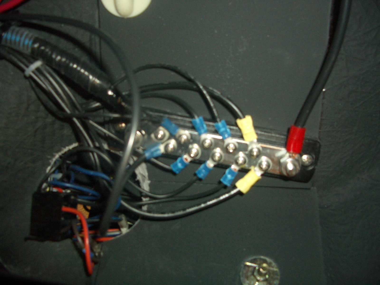
Once all the wires were ran, I put a 10 guage female spade connector on all the ends. Now onto the switches! The Johnson pumps I ordered did not come with any switches and the stock switches will not work for these pumps. The switch needs to be a double pole-double throw type switch. When you order your switches, make sure they are also the right size to fit into your dash. The stock Centurion switches are Contura switches. Here is a link to the Contura switches I purchased for this install.
Contura 12981 - 3 position On/Off/On switch
The new Contura switch will fit into the stock Centurion switch holes. The covers on the new switches were different than the stock Centurion switches but since they are the same brand it makes it easy to just switch the covers with the stock covers. To remove the cover from the switch just use a small flat head screw driver to release the tiny tab on each side of the switch cover that holds it onto the base. This was easy to do and made it so I could use my new switches but have them look exactly like the stock ones. Very Nice!
The switch wiring instructions that came with the Johnson pump are helpful but are not exact for this type of switch since the post numbering is slightly different and also my switch has an LED. So use the pump instructions only as a general guide.
The following diagram shows how to wire the new Contura switches I listed above.

Note that the dotted lines in the diagram are representing jumper wires between posts. For example, for the port switch you connect the Red wire from the pump to post 6 and then run a wire from post 6 to post 1. This allows the switch to reverse polarity to the pump which makes it spin in reverse. Also note the jumper wire going from post 5 over to post 7. This is to get the LED to work. The two switches are essentially wired the same with the exception of posts 3 and 6. Those are wired opposite from one another due to the direction each pump is mounted under the seat.
The part of all this that had me scratching my head for a while is how to get a jumper wire between two posts. There wasn't enough room in a 10 guage female connector to fit two wires (one from the pump and the other being the jumper wire). I ran all over town trying to find a solution. I went to home depot, lowes, Auto Zone, and a local electrical supplier but they didn't have anything that would work. I then went to a marine shop nearby (Fred's Marine) and told them what I was trying to do. They had exactly what I needed! It is a spade connector that has a female end and then hooks around into another male spade. I hope that made sense because this isn't a very good picture of the part.

Here's a picture with the pump wire connected to it.

And lastly, here's a picture with it connected to the back of the switch (before I ran the jumper wire).

I was very happy when Fred's Marine brought that part out to me. They didn't have any for sale on the shelves but had some in the back for their own service work. So be sure to ask the service guy at your marine shop if you go looking for something like this because you might not find it available on the shelf.
I was then able to finish my switch wiring and decided it would be a good time at this point to test them out before I got everything put back into the dash. So I reconnected my battery and filled a 5 gallon bucket with a little bit of water. I then made sure all my valves were closed on my manifold and put one of my aux hoses into the bucket of water. I first turned my port switch to the Fill position and it blew bubbles in the bucket. I then switched it to the Empty position for a brief second and it began to suck water up the hose. Great! This meant that the wiring was correct. If I would have seen the opposite results then that would have meant that the wires coming from the pump needed to be swapped on the back of the switch. I would have needed to swap the wires on posts 3 and 6 (including their corresponding jumpers to posts 1 and 4). The switch was wired correctly though so no worries. I then did the same test with the starboard switch/pump. Everything worked great. The pump worked in the right direction and the LED on the switch also worked.
After I had the switches wired and tested, I then attempted to fit them back through the switch panel. I soon realized that due to the size of the wires and the extra space taken by the jumper wires that the switch would not fit. That was easily solved by removing the switch panel from the dash and then disconnecting the jumper wires from posts 3 and 6. That gave me enough room to put the switch housing into the panel and then I was able to reattch the wires to 3 and 6 from behind with the switch panel removed.
I then attempted to attach the switch panel back onto the dash and ran into another hang up. The wires from the back of the switches kept hitting the fiberglass backing behind the dash. There are only a series of randomly placed access holes in the backing. My switches didn't line up with one of the access holes so they were hitting the backing and causing the switches to get all tweaked. It didn't look or function well. This was due to the larger guage wires and also the jumper wires. These don't bend and flex into the space like the smaller stock wires did. Here's a picure from under the dash that shows the round access hole in the backing.

I didn't feel like making any of the holes bigger. I thought that would be difficult to do without damaging all the wiring running through there. So my solution was to move my ballast switches to a different location in the dash panel where they would line up with one of the access holes in the backing. This only meant that I had to move each of them one spot to the left. The following picture shows their final installed location.

Whew! All done! Now it is just time to clean up all the wire clippings etc.
Parts List
Below is a list of items needed for this ballast install. I found that, at least in my area, that it was cheaper to get my plumbing parts from a local plumbing/sprinkler shop rather than big box stores such as Home Depot or Lowes. I chose to use hose supplied by EVCO House of Hose because it was cheaper and I felt it was higher quality than the ballast hose provided by sites like wakemakers. Some guys are very particular about their custom install looking like it was installed from the factory. If that is important to you then this hose is not for you since it is clear with white ribbing instead of solid black.
Your parts will vary obviously depending on your design and whether or not you reuse any stock thru hulls, etc. Here is an exploded view of the parts. I found it helpful to create this type of drawing to figure out quantities for each part. (click the drawing for a larger view)

Plumbing
2 - Johnson Ultra Reversible 13.7GPH impeller pumps (shop around online, there are some deals out there)
100 feet - 1" ID hose (Part number 090-1 from EVCO)
50 feet - 3/4" ID hose (Part number 090-3/4 from EVCO)
1 - 1" barb x 1" barb x 3/4" FPT tee
1 - 3/4" MPT x 3/4" male garden hose thread adapter
1 - Garden hose bras end cap
1 - Female garden hose x female garden hose swivel adapter
1 - 1" barb tee
4 - 1" check valves (wakemakers)
3 - 3/4" check valves (wakemakers)
2 - 1" barb x 1" barb x 1" FPT tee
2 - 1" barb x 1" MPT elbow
3 - 1" barb elbow
3 - 3/4" barb elbow
2 - 1" chrome thru hull
1 - 3/4" chrome thru hull
9 - 1" MPT to 1" barb adapter
2 - 1" MPT to 3/4" barb adapter
7 - 1" PVC slip x 1" FPT adapter
2 - 1" PVC slip x 1" FPT elbow
7 - 1" PVC slip tee
8 - 1" PVC slip ball valve
2 - 1" PVC threaded ball valve
3 feet 1" PVC pipe
2 - 1" MPT x 1" FPT street elbow
2 - 1" close nipple
2 - 3/4" barb plug
1 - roll of thread seal tape
6 - Fly High 1" Quick Release elbow (W746)
6 - Fly High 1" Quick Release x sac thread adapter (W743)
3 - Fly High 3/4" Quick Release elbow (W742)
3 - Fly High 3/4" Quick Release x sac thread adapter (W736)
2 - Fly High check valves (W744) for aux sacs
3 - 1" Y fitting (purchased from D&T Aquarium)
8 - boxes (10 pack) of hose clamps
8 - 1" #8 screws (if I remember right) for mounting pumps
1 - 3M 5200 Fast Cure marine sealant (for chrome thru hulls)
1 - small can of PVC primer
1 - small can of PVC glue
1 - PVC cutter
Electrical
6 - 10 guage wire assorted colors (length will vary)
8 - 10 guage butt connectors
2 - 10 guage ring connectors
22 - 10 guage female spade connectors
6 - spade jumper adapters (as shown in electrical section of this blog)
1 - 30 amp resettable breaker (may need two depending on what is in your boat)
2 - rolls of electrical tape
10 - 8" mounting zip ties
10 - 8" zip ties
10 - 14" zip ties
10 - 1/2" screws, #10. (for mounting zip ties)
1 - Wire stripper/crimping tool
2 - Contura 3 position DPDT switches (purchased here)
Garage Test
Once everything was complete and cleaned up, I decided to do a garage test and run water through each pump and all the lines to check for any problems or leaks. Remember the access tee that I placed in the supply line (shown in the pump installation section)? This is where that comes in handy if you don't like crawling under the boat with a fake-a-lake. Here's a picture of that again...
To do this test I used a 3/4" female hose thread x 3/4" female hose thread adapter screwed on the end of a garden hose. This adapter essentially just changes the end of the hose from male threads into female threads. Tragic if we weren't talking about a garden hose. :) Each end of this adapter spins to make it easy to use. Here's a picture of that part...

Here's a picture of it attached to the end of the garden hose.

Also notice the silver shutoff valve attached to the end. This is handy for shutting off the water supply without having to jump out of the boat. These parts will also come in handy using an old garden hose placed in a bucket of RV antifreeze when it comes time to winterize the ballast system.
Here's a picture of the hose attached to the ballast supply line.

I then shut the brass ball valve on the boat's intake thru hull. This will prevent the water from just going out the bottom of the boat. I then turned on the water. I quickly noticed that the water came up through the supply line and to the pump, but the pumps were shut off at this point so the water then diverted out each drain hose out the side of the boat.
I then turned on the starboard pump and the water no longer went out the drain hoses. The pump sucked the water up and into the starboard hard tank which I had opened the manifold valve to. I took a look around for any leaks and quickly noticed some spray coming from the Y fitting on the port side. I thought this was strange at first but then realized the starboard pump was sending water up through the manifold and to the starboard tank but was also sending water out the opposite side of the manifold and back down the opposite supply line because I had the isolation valve open on the manifold. So essentially the port side hose was pressurized by the starboard pump running. I simply didn't have my hose clamp tightened enough on the Y fitting. I then realized that the style of Y fitting I used required a very tight clamp to make it water tight under pressure. Not a big deal, just surprised me a bit.
Once I had that clamp tightened down and didn't see any other leaks, I shut off the garden hose and turned the switch to the drain position. I watched the water be diverted over the side of the boat at a fast rate just as I had hoped. Once the starboard tank was empty, I did the same thing for the port pump and checked everything for leaks.
Since I also used one of those Y fittings for the bow sac, I decided to open the valve to that sac and send water to it to make sure I didn't have any leaks out the clamps on that Y fitting. Everything checked out good. I was confident at that point that everything was working properly without leaks so I removed the garden hose, replaced the brass cap, and opened the thru hull ball valve.
Reinforcing Locker Dividers
The rear lockers of my Falcon V have removable dividers between the storage locker and the engine compartment. I had heard others say that it is possible for the 1100LB jumbo sac to flex the divider enough that it pops out of the channel that holds it in place. At first I was skeptical about that because my locker dividers seemed very strong. They didn't have any flex to them at all when I tried to bend them. But while I was doing my initial water test on the lake I heard a big bang about the time the sac was reaching capacity. I was quite startled by that and thought something had broke or the sac had burst. Fortunately the noise was just the locker divider being pushed out of the channel. Some other models of boats may not have this issue depending on how the metal frame around the engine compartment is built. My dividers have no middle support, it is only supported at the top and bottom which causes them to flex under the pressure of the fat sac.
To reinforce my locker dividers I went to Home Depot and purchased some 3/8" aluminum channel, 1" screws and small washers. I cut the aluminum channel into two 18" and one 12" sections. I then fastened the 18" sections to the large divider and the 12" section to the smaller divider. The channels are on the engine side of the divider so that they do not interfere with the fat sac. Below is a picture showing the completed dividers.


I then did another quick test at the lake to see if the reinforcement would hold the force of the sac and they appeared to be just fine. The dividers still flexed a little even with the aluminum but not anything significant.
Water Test and Pics of Wave
So we finally had a good weather day so I decided to head to the lake after work and dunk the boat in just long enough to do a quick test. I primarily surf goofy so that is all I tested. It was just my wife, 19 month old son and I. There wasn't any time to invite a third so that we could surf so this was just a quick outing to do a test. The water was still very cold anyway since this test was done on April 1st.
I began by filling up the integrated bow sac only. After about 6 minutes it was still not full so I became very curious why it would be taking so long. My hoses are clear and I could see pockets of air being sucked through them along with some water. I eventually realized that the pumps were sucking some air through my drain hoses. I have a check valve on each of them to prevent this from happening but apparently something was wrong with them. I called wakemakers where I purchased the check valves from and they didn't have a good solution for me. They said they use them in this type of installation all the time and never have an issue, especially with this brand of check valves. So I went back home and attempted to see if moving the check valves closer to the pump would help seal up the check valve better. The check valves appeared to not be sealing because there wasn't enough pressure to completely close the rubber flapper inside them. After a second water test, I found that moving the check valves closer to the pump did help a bit. They still did not initially seal up completely but I found that they can be forced shut by filling the sac for a few seconds and then switching the pumps to drain for a moment then switching it back to fill again. What happened when I did this was that it sent water into the drain hose which helped force the flapper closed once I switched to fill again. So having the check valves on the drain hoses located at a low point does help seal them up. That means that water will be in the drain hoses most of the time. That won't be a concern except when it comes time to winterize. I plan on sending RV antifreeze through my fill and drain hoses each winter so that will take care of any possibility of any water remaining in the hoses.
In previous posts, I mentioned that I usually had a sac on the seat and one on the floor behind the driver seat before I did the custom ballast. I found that with a jumbo sac in the locker that it produces just as good as a wave without the two additional sacs. That means that the new system produces the same wave as I had before without any sacs being visible. I was very pleased with that. It looked just as good but it is hard to say until I get a chance to surf it.
I then decided to fill up a 400lb sac on the floor behind the driver seat just to see what it would do. So still nothing on the seats. It definitely slammed the boat and made the wave a bit bigger. I was taking on a tiny bit of water through the side vent when under way. I never filled up one on the seat like I did with the old system. I'd for sure have to tape up my rear air vents if I was to do that. I might try it one of these days just to see what it looks like.
Anyway, sorry for the long story. I'll update this once I have a chance to do a better test and surf the wave. In the meantime, here's a video (wave only) of the two setups I tried out during this initial water test.
YouTube video of ballast test
UPDATE:
Here's a video of us surfing using the new ballast setup. The goofy side had 1100lb rear locker, 200lb starboard tank under bench seat, 400lb sac on floor behind driver, 400lb integrated bow sac, and the switchblade set at level 1. The regular side had the 1100lb rear locker sac, 400lb sac on top of bench seat pushed toward observers seat, 400lb integrated bow sac, switchblade set at level 2. Going 12mph on perfect pass (11.2mph GPS speed)
I began by filling up the integrated bow sac only. After about 6 minutes it was still not full so I became very curious why it would be taking so long. My hoses are clear and I could see pockets of air being sucked through them along with some water. I eventually realized that the pumps were sucking some air through my drain hoses. I have a check valve on each of them to prevent this from happening but apparently something was wrong with them. I called wakemakers where I purchased the check valves from and they didn't have a good solution for me. They said they use them in this type of installation all the time and never have an issue, especially with this brand of check valves. So I went back home and attempted to see if moving the check valves closer to the pump would help seal up the check valve better. The check valves appeared to not be sealing because there wasn't enough pressure to completely close the rubber flapper inside them. After a second water test, I found that moving the check valves closer to the pump did help a bit. They still did not initially seal up completely but I found that they can be forced shut by filling the sac for a few seconds and then switching the pumps to drain for a moment then switching it back to fill again. What happened when I did this was that it sent water into the drain hose which helped force the flapper closed once I switched to fill again. So having the check valves on the drain hoses located at a low point does help seal them up. That means that water will be in the drain hoses most of the time. That won't be a concern except when it comes time to winterize. I plan on sending RV antifreeze through my fill and drain hoses each winter so that will take care of any possibility of any water remaining in the hoses.
In previous posts, I mentioned that I usually had a sac on the seat and one on the floor behind the driver seat before I did the custom ballast. I found that with a jumbo sac in the locker that it produces just as good as a wave without the two additional sacs. That means that the new system produces the same wave as I had before without any sacs being visible. I was very pleased with that. It looked just as good but it is hard to say until I get a chance to surf it.
I then decided to fill up a 400lb sac on the floor behind the driver seat just to see what it would do. So still nothing on the seats. It definitely slammed the boat and made the wave a bit bigger. I was taking on a tiny bit of water through the side vent when under way. I never filled up one on the seat like I did with the old system. I'd for sure have to tape up my rear air vents if I was to do that. I might try it one of these days just to see what it looks like.
Anyway, sorry for the long story. I'll update this once I have a chance to do a better test and surf the wave. In the meantime, here's a video (wave only) of the two setups I tried out during this initial water test.
YouTube video of ballast test
Here's a video of us surfing using the new ballast setup. The goofy side had 1100lb rear locker, 200lb starboard tank under bench seat, 400lb sac on floor behind driver, 400lb integrated bow sac, and the switchblade set at level 1. The regular side had the 1100lb rear locker sac, 400lb sac on top of bench seat pushed toward observers seat, 400lb integrated bow sac, switchblade set at level 2. Going 12mph on perfect pass (11.2mph GPS speed)
Inland Surfer Mucus, etc from codyb25 on Vimeo.
Subscribe to:
Posts (Atom)